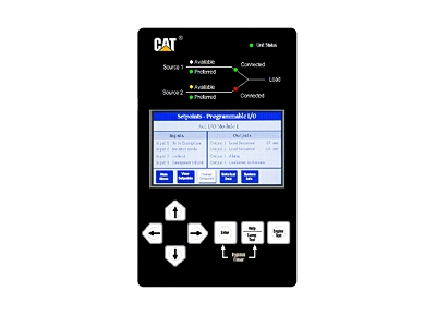
ATC-800 CONTROLLER
Technical Summary
- Rating Range
- 120 to 600V, single phase and three phase @ 50/60 Hz
- Transfer Type
- Switch application dependent
- Switch Type
- Switch application dependent
ATC Controller Specifications
- Input Control Voltage
- 120Vac (50/60 Hz) (operating range 65 to 160 Vac)
- Voltage Measurements of Utility
-
Source 1, Source 2 and Load
(VAB, VBC, VCA for Three Phase System) - Voltage Measurement Range
- 0 to 700 Vac
- Voltage Measurement Accuracy
- +/-1% of full scale
- Frequency Measurements Of
- Source 1 and Source 2
- Frequency Measurement Range
- 40 Hz to 80 Hz
- Frequency Measurement Accuracy
- +/- 0.1 Hz
- Undervoltage Dropout
-
Breaker Style 50 to 97% of Nominal System Voltage
Contactor Style - 78 to 97% - Undervoltage Pickup
- (Dropout +2%) to 99% of Nominal System Voltage
- Underfrequency Dropout Range
- 90 to 97% of Nominal System Frequency
- Underfrequency Pickup Range
- (Dropout +1 Hz) to 99% of Nominal System Frequency
- Overfrequency Dropout Range
- 103 to 110% of Nominal System Frequency
- Overfrequency Pickup Range
- 101% to (Dropout +1 Hz) of nominal system frequency
- Operating Temperature Range
- -20 to 70 degree C (-4 to +158 degree F)
- Operating Humidity
- Up to 90% Relative Humidity (non-condensing)
- Enclosure Compatibility
-
- NEMA 12 (std mounting)
- NEMA 3R
- UV Resistant Faceplate
Ratings
- System Voltage Application
- 120 to 600 Vac (50/60 Hz) (single or three phase)
Product Features
- True rms three-phase voltage sensing on Source 1, Source 2 and load
- Frequency sensing on Source 1 and Source 2
- Preferred source selection
- Programmable set points stored in nonvolatile memory
- Modbus communication to personal computer either on site or remote
- Viewable historical data on the most recent transfers (up to 16 events) are viewable at switch. Unlimited history storage (remote) available when used with remote software
- Load sequencing (optional)
- Engine start contacts (2 sets)
- Engine test switch with user-selectable test mode and fail-safe
- Alarm contact (multiple alarm functions available)
- Pretransfer signal (optional)
- Heartbeat monitor (flashing light signifies that the ATC-800 is operating properly)
- Instrumentation:
- Voltmeter (accuracy ±1%)
- Reads line-to-line on Sources 1 and 2 and load
- Frequency meter (40–80 Hz, accuracy ±0.1 Hz)
- Source available time (both sources)
- Source available time (both sources)
ATC-800 Programming
- Source 1
- Source 2
- Load History
- Time/Date
- Set Points
- Buttons provide easy access to all commonly used ATC-800 functions. When Source 1 is connected and the ATS is operating normally, the automatic indicator light will be flashing and the display window will be blank.
Using the Display Select button, the operator can step through each of the six display families:
Initial Programming
Factory programming will load all standard features and customer-specified options per the default settings.
Customer Programing
- Customers may reprogram set points and other parameters to match their application using the Program switch located on the rear of the unit. Once the programming mode has been activated and the Program light is flashing, the user may access Set Point settings by pressing the Display Select button until the Set Points LED is illuminated.
- Values for individual set points may then be altered by pressing the Increase (arrow up) or Decrease (arrow down) buttons. Once a parameter has been reset, the user advances to the next set point by pressing the Step button. While the ATC-800 is in the Program mode, the device continues to operate in accordance with the previously programmed set points and parameters.
- The unit is never offline and preset values do not change until programming has been completed. Once reprogramming is complete, the user may return the Program switch to the Run position. At this point, all new values are stored in the ATC-800 nonvolatile memory and the unit returns to Automatic mode.
Open Transition / In Phase Monitor
In-phase monitor is a feature that will allow a transfer between two sources only when the phase difference between the two sources is near zero. This is an open transition transfer that prevents in-rush currents from exceeding normal starting currents in the case where motor loads are being transferred.
Open Transition / Delayed with Load voltage
Load voltage decay transfer is a feature that, after opening the switch for the original source, holds in the neutral position until the voltage on the load is less than 30% of rated voltage. This operation is an open transition that prevents in-rush currents from exceeding normal starting currents in the case where motor loads are being transferred.
Operation
- Loss of normal power
- Open transition to alternate source
- Normal power restored
- Open transition back to normal source
- Test (user selectable)
- Load transfer—open transition to and from alternate source
- No-load transfer—starts alternate power source and allows to run unloaded; no transfer takes place
- The Cat ATC-800 transfer operates in the following modes:
Applicable Testing
- UL Recognized Component
- Meets Seismic Requirements of Uniform and CBC 2007 and IBC 2006 (exceeding requirements of worst case Zone 4 levels
- Complies with UL 991 environmental tests
- Complies with IEC 61000-4-2, 61000-4-3,61000-4-4,and 61000-4-5
- Complies with CISPR 11, Class A
- Complies with CSA 22.2-178
- Complies with FCC Part 15, Subpart B, Class A


